
Figure 1 A sketch of a typical three-phase oil-filled power transformer
Applicable Standards
The following international standards are commonly referenced in transformer design, testing, and forensic assessment:
- IEC 60076-5 – Power Transformers: Ability to Withstand Short-Circuit
- IEEE C57.12.00 – General Requirements for Liquid-Immersed Distribution, Power, and Regulating Transformers
- IEEE C57.104 – Guide for Interpretation of Gases Generated in Oil-Immersed Transformers
Introduction to Transformers
Transformers are critical components within electrical power systems, used to step up or step down supply voltages for transmission and distribution. They are broadly categorised into two types:
- Dry-type Transformers: Suitable primarily for indoor installations; the windings are not immersed in insulating liquid.
- Liquid-immersed Transformers: Suitable for both indoor and outdoor environments; commonly filled with insulating oil.
變壓器簡介
變壓器為電力系統中的關鍵設備,用於升高或降低電壓。變壓器主要可分為以下兩類:
- 乾式變壓器:主要適用於室內安裝,其繞組不浸於絕緣液體中
- 油浸式變壓器:適用於室內外環境,通常填充絕緣油進行冷卻與絕緣
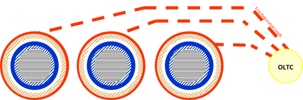
Figure 2 A sketch plan of the windings of the three-phase oil-filled power transformer
In a typical oil-filled transformer, each of the three phase windings has four layers of winding coils: two are low-voltage (LV) comprising an inner and an outer coil, and two are high‑voltage (HV) comprising a main and a coarse regulation (CR) / fine regulation (FR) coil. Each of the coils comprises many turns of copper conductors that are wrapped with paper insulation. The LV windings are arranged concentrically within the HV windings and wound onto a laminated steel core.
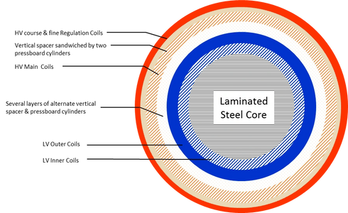
Figure 3 The internal construction of a winding phase of the three-phase power transformer
There are insulating spacers separating each individual concentric layer of LV and HV coils, constructed in cylinder pressboard sheets, and supported by vertical wooden spacers. The top & bottom of each winding are stacked with wooden blocks, and there are wooden structures compressing the blocks and the windings.
In most large transformers, there is an on-load tap changer (OLTC), which automatically regulates the voltage of the transformer in the event of load variation.
Power Transformers
Power transformers are utilised in electricity transmission systems and large-scale industrial facilities where high demand is constant. These units are typically rated from tens to several hundred MVA, with operating voltages starting at 33kV.
The life expectancy of a power transformer is generally more than 20 years of service, working within conducive environments. However, unusual service conditions can reduce its life expectancy. For example, operating outside the normal ambient temperature range (-20°C to 40°C), installed at high altitude (> 1000 m above sea level) & seismic conditions.
Transformers may be equipped with the following protection and monitoring devices:
- Liquid level indicator, a gauge that indicates the level of the insulation liquid
- Pressure relief device, releasing excessive internal pressures that may build up during service
- Temperature indicator, measures the temperature of the insulation liquid
- Winding temperature indicator, measures the designed hottest spot in the winding
- Sudden pressure relay, an electrically operated switch that detects a sudden increase in the internal pressure of the equipment caused by a fault in the winding tank
- Buchholz relay, an oil- and gas-actuated relay located in the pipe connecting the winding tank & the conservator (an external overhead oil reservoir). It detects faults in the winding tank
電力變壓器
電力變壓器廣泛應用於輸電系統及對電力需求較高的大型工業設施。此類設備的額定容量通常由 200 MVA 起,運行電壓高達 33 kV 或以上
Distribution Transformers
Distribution transformers step down voltage from transmission systems to levels suitable for end-users. They are generally rated at not more than 200MVA, with operating voltages no more than 11kV
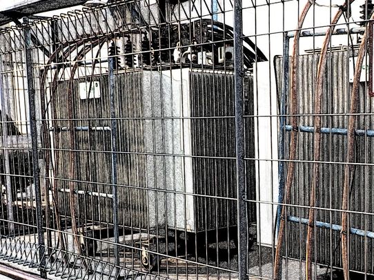
Figure 4 A sketch of a typical three-phase oil-filled distribution transformer
Rectifier Transformers
Are used in industrial processes running on direct current (dc) supply, such as dc traction, electrolysis, smelting operations & large variable speed drive trains. Power electronic circuits convert alternating current (ac) to dc, aka rectifier circuits. Power electronic circuits also convert dc to ac, also known as inverter circuits. A transformer that has one of its windings connected to either a rectifier circuit or an inverter circuit is respectively known as a rectifier transformer or a converter transformer
Dry-type Transformers
Have dielectric of a gas or a solid on their windings; the windings are not immersed in an insulating liquid
Shunt Reactors & Series Reactors
(aka Steady-state reactive compensation & Current limiting reactors, respectively) Are used in electrical power systems to limit over-voltages or heavy/short-circuit current in power transmission
Shunt Reactors stabilize voltages during load variations. Long HV voltage transmission lines generate a substantial amount of leading reactive power when the supply lines are lightly loaded. Conversely, they absorb a large amount of lagging reactive power when the supply lines are heavily loaded. Without reactive power balancing, the rated voltage on the transmission lines cannot be maintained under load variations.
Series reactors protect against excessively large currents under short-circuit or transient conditions. Applications include motor starting and electric arc furnace (EAF)
Instrument Transformers
Isolate the transmission systems or mains supply circuit with the control & measuring devices, by magnetically coupling both circuits. They step down hazardous voltages or currents to a safe level for measurement or monitoring. Instrument transformers comprise current transformers (CTs) and voltage transformers (VTs)
Current Transformers (CT)
Couple high current lines with the monitoring devices. The primary winding of the CT is connected in series with the load current-carrying conductor. The secondary winding proportionally transforms the primary levels to typical values of 5 A for metering applications, such as wattmeters, power-factor (PF) meters, voltmeters, ammeters & relays
Voltage Transformers (VT)
(aka Potential Transformers) Reduce hazardous high voltages to a level that can be safely applied to voltmeters or protective relays. The primary winding of the VT is connected in parallel with the monitored circuit. The secondary windings proportionally transform the primary levels to typical values of 120 V, for metering applications, such as wattmeters, power-factor (PF) meters, voltmeters, ammeters & relays
Investigation of Transformer Failures
Objectives of Investigation
- Determine compliance with regulatory requirements and insurance policy conditions
- Assess the suitability for continued operation
- Identify potential avenues for recovery of financial losses
- Identify indicators of fraudulent claims
- Transformer failures may result in physical damage, operational downtime, and significant business interruption losses
Investigation Process
- Collection and review of all relevant data
- Site attendance to assess operating conditions and application parameters
- Interviews with personnel familiar with the equipment
- External inspection and preliminary testing
- Detailed internal inspection following untanking, preferably at the original equipment manufacturer (OEM) or a specialised facility
- Analysis of operational history and technical records
- Preparation of a comprehensive forensic report
Key Considerations
- Protection device trips or alarms, repair history and abnormal diagnostic test results
- Design specifications, manufacturer details and technical drawings
- Historical performance and failures of similar transformer models
- Deviations from factory test results or standard operating practices
事故調查流程
在變壓器吊芯(Untanking)後進行詳細的工程鑑識檢驗。此程序建議於原廠(OEM)或具備專業設備的維修廠進行,以便對繞組進行深度檢查
Dissolved Gas-in-oil Analysis (DGA)
DGA is a primary diagnostic technique for detecting incipient fault conditions in oil-immersed transformers. Analyzing historical DGA trends is essential in identifying evolving failure mechanisms. Test results of the DGA for several years can assist in the trending of the failure mechanism of the equipment
The key gases of DGA are hydrogen (H2), methane (CH4), acetylene (C2H2), ethylene (C2H4), ethane (C2H6), carbon monoxide (CO) and carbon dioxide (CO2). With the exception of CO2, the remaining six gases are combustible. The following are indicative of specific fault conditions:
- High carbon monoxide & carbon dioxide indicate thermal or oxidative damage to cellulose insulation. If there were high carbon monoxide detected but no reports of previous overloading events or indications of thermal problems, it could suggest excessive oxygen in the oil
- High oxygen suggests inadequate oil processing or gasket leaks
- Acetylene indicates arcing or events of very high temperatures
- High hydrogen with methane in an approximate ratio of 1:5 suggests partial discharge activity
油中溶解氣體分析
油中溶解氣體分析(DGA)是鑑定油浸式變壓器潛伏性故障(Incipient Faults)的首要診斷技術。透過分析歷年的 DGA 數據趨勢,能有效識別設備內部演變中的失效機制
Oil Insulation Test
Examples include:
- Reduced dielectric strength – possible contamination or excessive moisture
- Increased moisture content – may indicate moisture ingress into paper insulation
Winding Ratio Test
Winding ratio that was different from the factory test record indicates electrical shorting of the winding. The shorting can occur between turns (aka inter-turn shorting) or between windings, such as disc-to-disc
Polarization Index (PI)
Indicates the moisture and possible deposition of conductive dust particles on the surface of insulation material
A polarization index (PI) value of less than 2.0 indicates deterioration of insulation
Excitation Current Test
Detects winding problems including unintended movements caused by mechanical impact (for example, transportation) or electromotive force that was produced when supplying high current to an external short-circuit event
Partial Discharge (PD) Measurement
Detects for any localised dielectric breakdown or deposits of conductive dust particles on solid insulation of the windings
Applied Voltage (Hi-Pot) Test
Tests the insulation between two windings, or between the windings & the earthed chassis
Frequency Response Analysis
Evaluates any displacement of the transformer core, windings and the holding structures
Inspection of the Transformer Windings
Following the inspection of equipment on the site and collection of the background information, it is often necessary to inspect the internal windings of the transformer for any physical evidence of the failure. The process should be directed by a person having knowledge of the equipment. Untanking of the transformer windings is best undertaken in the manufacturer’s facility, where hoist equipment, tools for dismantling & test equipment are available to facilitate the inspection, and manufacturer’s engineers are available for discussion. Internal inspections focus on identifying evidence of:
- Electrical tracking or flashover marks between separate windings, or a winding & earthed ground
- Mechanical distortion or signs of movements of coils or windings resulting from through-fault currents
- Inter-turn or inter-disk insulation failures
- Conductive contaminants within the solid insulation
- Loose or misaligned spacers
- Faults at the magnetic circuit
The steel cores are surrounded by the transformer windings and are laminated to reduce eddy-current. They concentrate the magnetic flux of the windings. Due to manufacturing defects, poor maintenance, or contamination, the laminated steel core may develop localised heating. Signs to look for,
- electrical arcing at the laminated steel core
- leakage flux heating in the outer laminations and at joints, edges, earthed steel core & lock plates
- mechanical distortion in the laminated steel core
繞組內部檢驗重點
內部勘驗重點在於識別以下證據:
- 繞組與接地組件之間的電氣追跡(Tracking)或閃絡痕跡
- 由外部短路電流(Through-fault currents)引起的線圈位移或變形
- 線圈匝間或盤間的絕緣失效
- 固體絕緣物中的導電污染物
Common Failure Mechanisms
Transformer Tank
Winding tanks contained insulation oil, which acts primarily as an insulation medium & cooling for the windings. Leaks at the tank wall can occur due to corrosion, thermal cycling or weld cracks, resulting in the reduction of the oil level and the ingress of moisture. Insufficient cooling oil can lead to overheating of the windings
Transformer Radiators & Coolers
Occurrence of leaks can lead to the ingress of moisture, which reduces the dielectric strength of the insulation oil
Impediment to the flow of insulation oil reduces the cooling efficiency for the windings. Loss of cooling can also be associated with malfunctioning fan motors. As a result, the operating temperature of the transformer increases, which causes a corresponding decrease in the capacity of the equipment
Dielectric or Insulation Integrity
The primary cause of transformer failure is the degradation of the winding's dielectric insulation. This can result from thermal ageing, moisture ingress, inadequate maintenance, defective material, mechanical damage associated with vibration, or mechanical stress associated with external faults
Oil deterioration caused by conductive particles or moisture can initiate electrical discharges, leading to insulation degradation and eventual failure
Short-Circuiting
High level of electromotive forces in the event of a short-circuiting fault at the load circuits can lead to movements in the winding turns. In some severe situations, the winding displaces or buckles, causing abrasion to the windings’ paper insulation to the extent that conductors are exposed. Subsequently, localised arc damage can occur at one or more points of the winding turns
Transformer Bushings
Are insulating devices that allow an electrical conductor to pass safely through the grounded winding tank of the transformer. Common mechanisms that lead to bushing failures include leaks, projectiles and defective porcelain or polymer insulator. Problems of thermal instability in bushings can result in separation of seals. Deteriorated seals in terminal connections can lead to the ingress of moisture, which permeates into the oil & paper insulation, degrading the dielectric medium. Projectiles can shatter porcelain sheds
Overvoltages
Originate from external sources. Overvoltages produced by lightning activity are more significant in the vicinity thunderstorms. Overvoltages in the transmission lines are transients associated with switching operations at the power station
Load Tap Changers (LTC)
Regulate voltage levels of the transformer by either adding or removing turns from the secondary winding, thus, maintaining the desired voltage at varying loads. Problems associated with LTCs include misalignment of contacts, poor design of the contacts, high loading and component failures, which include failures of springs, bearings, shafts & drive mechanisms. Excessive wearing can cause contact failure
Copyright © 2018 - 2026 efe Consultants Pte Ltd. All rights reserved.
Forensic Engineering | Electrical Failures | Fire & Explosion Investigations
Based in Singapore, serving clients worldwide
Privacy Policy